
They look like the exact same arms. I spent last night looking at every video I could find and nothing is similar to mine! I have spent a couple hours tinkering this morning. With the LCA attached and the compressor installed there is no way the spring can be installed! To use the compressor the LCA must be unbolted and 2 jacks used. I think I can get it in place with the compressor removed.

View attachment 740066They look like the exact same arms. I spent last night looking at every video I could find and nothing is similar to mine! I have spent a couple hours tinkering this morning. With the LCA attached and the compressor installed there is no way the spring can be installed! To use the compressor the LCA must be unbolted and 2 jacks used. I think I can get it in place with the compressor removed.
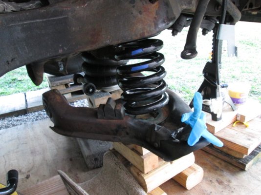
What is highlighted in red is exactly what my posts earlier address. You can't get the spring in or out with the compressor in it because the rod through the hole hits or you have to have arm too high to get the spring in the tower. The procedure works very well on our generation van, but they are a bit different.
As I described it, the easiest way is to support the arm on outboard extreme just in side the ball joint on the front leg of the arm.
Then put a jack under the rear leg of the arm just outboard of the rear pivot on that side. Play with the two jacks until the bolt is easy to remove from pivot on the rear leg and then go to front pivot and tap the bolt forward enough to come out of the rear hole in the frame so not holding that side up.
You can then lower the rear pivot point down, possibly also lowering the front jack some. See my pic with tilted arm.
You should (I can on our current model) get the arm tilted enough to get the spring in so you can start lifting the rear to tilt it back up until the spring can be tilted into the tower.
Then lift the front and rear jacks as needed to get the rear pivot bolt back in halfway.
Sometime is best to get front bolt through the rear frame hole first then rear, but could be either way. The the front first and it it doesn't go do the rear then try the front.
If you take the arm all the way loose, it will take 3 jacks and at least two people to manipulate them. It is also very difficult to do as the spring weight makes it much hard than just the arm
If you do decide to try the completely unbolted in the rear routine, when you reassemble and try to get the pivot bolts back in, get one of the jacks under the compressor rod so you can hold the weight of the spring off the arm as that will make it easier.
Best of luck to you!Thanks for the long response, greatly appreciated. I will try to follow your directions as my way is not working.
That is interesting as I can pull ours all the way on the rear for several inches.
I can't tell exactly where you have the outboard jack, but it needs to be on front leg a bit inboard from the balljoint. The goal is to let the arm pivot around the jack and front pivot bolt. Lowering the front jack might also help as well as pulling the rear pivot somewhat outboard before down.
It is odd that your control arm is opposite in design to ours, with the front pivot being the shorter and wider bushing. Perhaps reversing which end gets removed and which only partially could make it work better.
Side thing. What is the blue piece in the bottom of the spring pocket? It is covering up the pocket for the spring tail. Most only use a rubber damper on the top, if that.
I played with the front jack, moving it around and up and down, was no help.
The bright blue is a glove taped to the ball joint, lawn guy comes and blew half the loose stuff in the yard on my nice greasy ball joint.
In the bottom of the spring pocket, it is some kind of rubber that was there when I took this apart. With 75K miles I doubt the front has been apart before. I have not seen it listed anyplace as a replacement part.
Rubber thing moves around while I am trying to do anything. So I glued it in and marked the end of the spring tail pocket with red marker. Also did another reference point in paint.
Top rubber buffer moves around like a slinky so I put a couple wraps of electrical tape on it. Will need to figure out some jacks tomorrow.
Top rubber buffer moves around like a slinky so I put a couple wraps of electrical tape on it. Will need to figure out some jacks tomorrow.
Attachments

That is very close to the same as the one I made to lift the front of our JD lawn tractor from the front deck mounting brackets. I am lucky in that I have a metal working shop in my garage with a mill and lathe plus supporting cast so I can still make stuff like that pretty easily. I have a lot of homemade tools accumulated over the years.Poking around the net and a picture of a home made SST was posted. Back in the day I could have built this.
When I read articles about this I get the impression they are leaving the steering knuckle connected when they remove/replace the spring??
You can leave the steering knuckle in, I have done that, it is best to leave it connected to one of the ball joints and not both as it gets pretty heavy and had to maneuver with it all assembled especially if you leave the hub and brakes parts on also. It is easy to remove so I do.
Were they doing Express vans?
This was on an S10 forum from long time ago, they were talking about the same SST part # I also found a picture using the SST with the knuckle still in place. But is it a photo shoot or are they actually working on the vehicle?
Picture shows as a pdf, wonder if it will show when I post? Edit: I tried to post the picture but it brings the whole article, SST picture is #8
Picture shows as a pdf, wonder if it will show when I post? Edit: I tried to post the picture but it brings the whole article, SST picture is #8
Attachments
That looks like a whole different setup with all the parts they have added, plus it is a very soft spring. It is also is apparent from the instructions that you and just set the spring in without issue with it all in place and don't have to compress it.This was on an S10 forum from long time ago, they were talking about the same SST part # I also found a picture using the SST with the knuckle still in place. But is it a photo shoot or are they actually working on the vehicle?
Picture shows as a pdf, wonder if it will show when I post? Edit: I tried to post the picture but it brings the whole article, SST picture is #8
The tool they have is just for lifting the rear arms into the frame mounts and they don't seem to have to compress the spring much at all to do that as they have very little mechanical advantage on the jack to spring. I have done similar with my flat top scissors transmission jack when I was testing and just putting in the arm without the spring and it worked fine. It would never be able to lift heavy enough to move the rear mounts with the spring in place on a van.
That is probably some kind of offroad or race suspension kit and those often are setup for fast spring changes do they can match rate to the course or track.
I do not have the back ground or tools you have. I did go to school and worked as a welder in fabricating shops decades ago. Also had some machine shop training back then. Found a job where I could sit and look out the window and went with that. Looking through my meager collection of treasures I did find 2 3" X 3"X 3" angle iron which I may be able to use to make the uprights on the cradle. Then I would need a U channel for the cross bar. In one article they did mention 3/8" 3" U channel for the cross bar. Would that be over kill?
It all depends on if the spring is compressed our not. If it is you will be lifting a hundred pounds or so. If it is no compressed it will lifting in the 1000s of pounds.I do not have the back ground or tools you have. I did go to school and worked as a welder in fabricating shops decades ago. Also had some machine shop training back then. Found a job where I could sit and look out the window and went with that. Looking through my meager collection of treasures I did find 2 3" X 3"X 3" angle iron which I may be able to use to make the uprights on the cradle. Then I would need a U channel for the cross bar. In one article they did mention 3/8" 3" U channel for the cross bar. Would that be over kill?
The killer is that there is nothing to keep the two arms from rotating around the balljoint, or the spring support if it is not compressed. A single lift jack with not restrain that rotation, and that is why two separate jacks with one on each arm work better. You may need more lift on one or the other arm also.
Thanks for the input always appreciated. I am sure you are right about 2 jacks, however I have little room to use 2 with all my blocking under there, if I have to I can rearrange everything. It seems the force needed to lift the arm cannot be too much or I will be lifting the van.
I have been enjoying tinkering with this and will try it before I try 2 jacks.
I have been enjoying tinkering with this and will try it before I try 2 jacks.
Attachments

I don't think I would go that far, mostly because the springs are just like other brands and they also are following correctly the physics of spring design.I have a great neighbor who has an amazing back ground, machinist, to race cars to helicopter mechanic. He is of the opinion that Moog used the thicker coils so they could use a cheaper steel.
The replacement springs like these are meant to be higher spring rate, and you get higher spring rate by making the spring wire a larger diameter. I this case going from .870" or 1.000" wire to the 1.03" wire these are made of.
The biggest issue for the issue of being able to get the cam bolt out is because of the higher number of coils, which leaves less space between the coils.
Higher coil counts/lower wind angle is normally considered a better spring as the the lower wind angle gives less progressivity so less change of rate with compression.
What really seems to be an issue, I think is the heat treating and draw of the springs as that can easily make a spring much more stiff or soft.
That said, the Moog springs have changed compared to about 5 years ago. On the later model Chevies they run over an inch higher ride height but have the same dimensions as the older ones.
Production was moved from North America to China and that is when it changed. My guess is they have to supply certification of material to Moog, so it is probably correct, although all specs have a range that is acceptable. Forging certs happens but is very risky for even a Chinese company. In my experience, the hardening process is quite consistent, but the drawing the hardness back down to final spec can be harder to hit just right. It is done by holding the spring at elevated temp for an amount of time.
Similar threads
Try RV LIFE Pro Free for 7 Days
- New Ad-Free experience on this RV LIFE Community.
- Plan the best RV Safe travel with RV LIFE Trip Wizard.
- Navigate with our RV Safe GPS mobile app.
- and much more...