Journey with Confidence RV GPS App RV Trip Planner RV LIFE Campground Reviews RV Maintenance Take a Speed Test Free 7 Day Trial ×


Reply
 
Thread Tools Display Modes
 
Old 04-03-2018, 02:10 PM   #41
Platinum Member
 
Join Date: Aug 2010
Location: Minnesota
Posts: 12,410
Default

Interesting information from the manual posted.

I really don't see a lot of issues with what they say, and I think my first impression would be to think that what they have is basically not bad.

In shore power operating they have the shore power ground fed through the box to the output ground and not bonded to the neutral so that is all fine. The question of whether or not this is safe in relation to the the chassis being grounded or not to the shore ground should not be an issue because the ground buss bar in the main box will be grounded to the chassis. There would be continuous ground from the chassis to the shore power pole. The neutral and ground would not be bonded in the van unless the extra wire to the breaker box was in place, which is still odd at this point.

When the shore power is disconnected, the inverter disconnects the shore power ground feed through to the output ground and at the same time connects the output neutral and ground to bond them. This also looks to be fine as the inverter is ground and neutral bonded at the source and the chassis is still grounded to the ground wiring at the breaker panel. The only thing that isn't grounded is the shore power cord and that doesn't matter as it not connected to any power source or carrying any current.

My guess would be that they put the little wire jumping the grounds on so that a GFCI or other item wouldn't see an open ground on the cord while for the instant when plugging in and trip. Once plugged in the ground is complete. Using a big wire on it won't hurt anything, either, and in the Magnum drawing, that is how they did it, as they show the ground going through the box all the time. Of course, with the jumper on, you also stand the chance of a device seeing the neutral and ground connected and not liking that, so it goes both ways.

Personally, if I am looking at the setup correctly, and that is the right manual, I don't see a hazard with any of the scenarios. No jumper, small jumper, big jumper all would appear to be safe.
booster is online now   Reply With Quote
Old 04-03-2018, 02:25 PM   #42
Platinum Member
 
Join Date: Mar 2018
Location: California
Posts: 132
Default

Quote:
Originally Posted by ContinuousImprovement View Post
Warning authored in tiny screen late at night.
Shore cable ground lugs? Buss bars? Autobond? I wish these words applied to the Hymer/ecotrek shore power design.
The attached picture shows an interior view of the inverter's I/O terminal block AFTER our Aktiv.was made safe by adding the 10 gauge green wire. From Hymer, only the shown 18 gauge green/yellow wires are between the top and bottom set screw terminals.

Externally the shore power's cable is attached here and only here. The top connection is shore safety ground to the 18 gauge wire. The next down is HOT to the internal red 12 gauge wire routed to inverter electronics. The third setscrew externally connects to shore neutral and internally to a black 12 gauge wire to the inverter electronics.
The bottom three setscrew terminals are the inverter's output. Fourth is neutral, fifth is HOT and bottom is safety ground to the breaker box. Ignoring my added 10 gauge green wire, the ONLY connection from shore ground and the breaker box ground cable is the yellow/green 18 gauge wire. Not shown in the picture available on vacation is the internal crimped lug that splices the two 18 gauge wires togethee and is attach internally to the painted chassis.

Your last paragraph starts to explore, "how did hymer make such a dangerous mistake". Even the best engineer makes mistakes. The better question is who reviewed? Even the best factory technician makes mistakes. Why couldn't RVIA inspectors see the blaten defects and stop shipment? Why did the Aktiv pass RVIA certification? Is the confusingly labled breaker box cable as SHORE POWER an intentional error?

I suspect that safety priority and design/mfg process are lacking. I detect Hymer managment has created an environment of "ship the product" and CYA. Problems are buryed instead of fixed.
Do not do this at home! This is a job for a trained technician following engineering instructions. I'm an EE, ipc-610 trained, wore an ESD coat and followed standard ESD procedures. I take no responsibility for anyone altering their electrical system.
Many might ask why the 10 gauge wire is on the inside the inverter. Let's not sidetrack the grounding safety discussion and hunt for an regulatory on that subject.
ContinuousImprovement is offline   Reply With Quote
Old 04-03-2018, 02:33 PM   #43
Platinum Member
 
Join Date: Mar 2018
Location: California
Posts: 132
Default

Quote:
Originally Posted by BBQ View Post
The RVIA is a trade association of RV manufacturers and component parts suppliers.

I don't see how a trade association can police themselves on such highly technical matters.

The RVIA has a certification program used voluntary by it's members. If I understood the RVIA official, it includes certification and 7-week sampled on site inspections.
ContinuousImprovement is offline   Reply With Quote
Old 04-03-2018, 03:39 PM   #44
Platinum Member
 
Join Date: Dec 2010
Posts: 2,058
Default

I will say this. After studying your plan of attack with regulators and certification agencies I can see why You have worried roadtrek. Usually they are hit by lawsuits from individuals whom they can outspend.

By hitting them in a 'sneak attack' from behind with these agencies-they are people who can out spend and regulate them
gerrym51 is offline   Reply With Quote
Old 04-03-2018, 11:10 PM   #45
Platinum Member
 
Join Date: Mar 2018
Location: California
Posts: 132
Default

Quote:
Originally Posted by booster View Post
Interesting information from the manual posted.

I really don't see a lot of issues with what they say, and I think my first impression would be to think that what they have is basically not bad.

In shore power operating they have the shore power ground fed through the box to the output ground and not bonded to the neutral so that is all fine. The question of whether or not this is safe in relation to the the chassis being grounded or not to the shore ground should not be an issue because the ground buss bar in the main box will be grounded to the chassis. There would be continuous ground from the chassis to the shore power pole. The neutral and ground would not be bonded in the van unless the extra wire to the breaker box was in place, which is still odd at this point.

When the shore power is disconnected, the inverter disconnects the shore power ground feed through to the output ground and at the same time connects the output neutral and ground to bond them. This also looks to be fine as the inverter is ground and neutral bonded at the source and the chassis is still grounded to the ground wiring at the breaker panel. The only thing that isn't grounded is the shore power cord and that doesn't matter as it not connected to any power source or carrying any current.

My guess would be that they put the little wire jumping the grounds on so that a GFCI or other item wouldn't see an open ground on the cord while for the instant when plugging in and trip. Once plugged in the ground is complete. Using a big wire on it won't hurt anything, either, and in the Magnum drawing, that is how they did it, as they show the ground going through the box all the time. Of course, with the jumper on, you also stand the chance of a device seeing the neutral and ground connected and not liking that, so it goes both ways.

Personally, if I am looking at the setup correctly, and that is the right manual, I don't see a hazard with any of the scenarios. No jumper, small jumper, big jumper all would appear to be safe.
The manual is not correct. I posted a picture of the shore power ground being hard wired to the 18 guage wire. 18 gauge is too small as a safety ground for 30 amp shore power. Do you agree?
ContinuousImprovement is offline   Reply With Quote
Old 04-03-2018, 11:43 PM   #46
Platinum Member
 
Join Date: Aug 2010
Location: Minnesota
Posts: 12,410
Default

I think the manual may be correct, but Roadtrek didn't wire it that way. The manual shows the shore power cord ground going to the input side strip connection with the hot and neutral, so it should be 12ga if that is what the cored is. They also state that with that connection, when on shore power the inverter will connect that ground to output ground, which is connected to the chassis. I would call that fine and safe with full size ground and no extra bonding except for the Roadtrek dumb jumper to neutral in the breaker box. Why Roadtrek chose to use a piece of 18ga in the circuit is anybodies guess, although I think it would be a mistake, just like the the 18 ga to the neutral bar of the breaker box.

Until Roadtrek tells someone how it is supposed to be wired by them, nobody will really know if the problems were intentional or a mistake at assembly. Unfortunately, Roadtrek will never release any wiring diagrams, so it is unlikely we will ever know unless someone else with a similar van can look and see how there's is wired.
booster is online now   Reply With Quote
Old 04-04-2018, 01:35 AM   #47
Platinum Member
 
Join Date: Mar 2018
Location: California
Posts: 132
Default

Quote:
Originally Posted by booster View Post
I think the manual may be correct, but Roadtrek didn't wire it that way. The manual shows the shore power cord ground going to the input side strip connection with the hot and neutral, so it should be 12ga if that is what the cored is. They also state that with that connection, when on shore power the inverter will connect that ground to output ground, which is connected to the chassis. I would call that fine and safe with full size ground and no extra bonding except for the Roadtrek dumb jumper to neutral in the breaker box. Why Roadtrek chose to use a piece of 18ga in the circuit is anybodies guess, although I think it would be a mistake, just like the the 18 ga to the neutral bar of the breaker box.

Until Roadtrek tells someone how it is supposed to be wired by them, nobody will really know if the problems were intentional or a mistake at assembly. Unfortunately, Roadtrek will never release any wiring diagrams, so it is unlikely we will ever know unless someone else with a similar van can look and see how there's is wired.
Thanks Booster. You wrote, "They also state that with that connection, when on shore power the inverter will connect that ground to output ground, which is connected to the chassis. ". That sentence implies the inverter is dynmically controls the safety ground but I sent a picture proving it is hardwired to 18 guage (no switch).
I would says it Hymer instation's fault for not running 12 gauge outside the inverter.

I appreciate how are sticking with the "design review". I will be home tonight, and draw the schematic. No one has discussed the hot water heater going boom

I'll post a new clean thread with the schematic. We are almost on the same page but no.GOV have joined the discussion. Is there another site that might get a hit?
ContinuousImprovement is offline   Reply With Quote
Old 04-04-2018, 01:42 AM   #48
Platinum Member
 
Join Date: Mar 2018
Location: California
Posts: 132
Default

Quote:
Originally Posted by gerrym51 View Post
I will say this. After studying your plan of attack with regulators and certification agencies I can see why You have worried roadtrek. Usually they are hit by lawsuits from individuals whom they can outspend.

By hitting them in a 'sneak attack' from behind with these agencies-they are people who can out spend and regulate them
I really don't understand why Hymer has taken my notifications as an attack. I design avionic systems and safety is reached with layers of overlaping help.and reviews. I've avoided the press but it would be easy to have an "expert inspector" say scary things on camera.

The goal is Quality and it's partner, Safety. Why should that be so hard?
ContinuousImprovement is offline   Reply With Quote
Old 04-04-2018, 02:23 AM   #49
Platinum Member
 
Join Date: Aug 2010
Location: Minnesota
Posts: 12,410
Default

Quote:
Originally Posted by ContinuousImprovement View Post
Thanks Booster. You wrote, "They also state that with that connection, when on shore power the inverter will connect that ground to output ground, which is connected to the chassis. ". That sentence implies the inverter is dynmically controls the safety ground but I sent a picture proving it is hardwired to 18 guage (no switch).
I would says it Hymer instation's fault for not running 12 gauge outside the inverter.

I appreciate how are sticking with the "design review". I will be home tonight, and draw the schematic. No one has discussed the hot water heater going boom

I'll post a new clean thread with the schematic. We are almost on the same page but no.GOV have joined the discussion. Is there another site that might get a hit?
I guess I am missing the point here. I understand you had pix of external wiring that was not adequate. The fact that there was no switch, when the manual says it connects the shore power ground through to the output ground, completing the circuit, is because Hymer didn't use one. The switch referred to in the manual would be internal to the inverter and likely tied in with the switching that does the autobonding when inverting.

I understand the issues with your van, but what I am saying is that if the inverter were wired as the posted manual said, I don't see any reason it would not be safe and legal. This is vitally important in the real world of products, safety, and liability because if the manual is correctly done to provide a safe product, the manufacturer is mostly off the hook for liability or penalties. At that point you have two other things that could have happened. One is that the assembler messed up and got the wiring wrong, which is a lesser problem to Hymer than if they intentionally went against the manufacturers specifications, as they would be mainly on the hook for poor training and not intentional decisions. If they chose to wire the unit as your van was, contrary to the manufacturers manual and specifications, there potential problems grow exponentially in most cases.
booster is online now   Reply With Quote
Old 04-04-2018, 02:16 PM   #50
Platinum Member
 
Join Date: Dec 2010
Posts: 2,058
Default

[QUOTE=ContinuousImprovement;69993]I really don't understand why Hymer has taken my notifications as an attack. I design avionic systems and safety is reached with layers of overlaping help.and reviews. I've avoided the press but it would be easy to have an "expert inspector" say scary things on camera.

The goal is Quality and it's partner, Safety.

if your crusade with regulators forces hymer/roadtrek to recall all Ecotrek installed models it could possibly put them under.

Of course they see it as an attack
gerrym51 is offline   Reply With Quote
Old 04-04-2018, 06:04 PM   #51
Platinum Member
 
Join Date: Mar 2018
Location: California
Posts: 132
Default

Quote:
Originally Posted by booster View Post
I guess I am missing the point here. I understand you had pix of external wiring that was not adequate. The fact that there was no switch, when the manual says it connects the shore power ground through to the output ground, completing the circuit, is because Hymer didn't use one. The switch referred to in the manual would be internal to the inverter and likely tied in with the switching that does the autobonding when inverting.

I understand the issues with your van, but what I am saying is that if the inverter were wired as the posted manual said, I don't see any reason it would not be safe and legal. This is vitally important in the real world of products, safety, and liability because if the manual is correctly done to provide a safe product, the manufacturer is mostly off the hook for liability or penalties. At that point you have two other things that could have happened. One is that the assembler messed up and got the wiring wrong, which is a lesser problem to Hymer than if they intentionally went against the manufacturers specifications, as they would be mainly on the hook for poor training and not intentional decisions. If they chose to wire the unit as your van was, contrary to the manufacturers manual and specifications, there potential problems grow exponentially in most cases.
Thanks Booster. I drew the grounding schematic. I'm starting a new thread and keeping it simple this time.
ContinuousImprovement is offline   Reply With Quote
Old 04-04-2018, 06:26 PM   #52
Platinum Member
 
Join Date: Aug 2010
Location: Minnesota
Posts: 12,410
Default

I have been rereading this thread. In the initial article it said that the shore power ground was hooked up only to the inverter input AC terminal strip, but then says it was reduced to size 18ga and connected to the inverter chassis (on paint). Does this mean that there was an 18ga wire from the terminal strip to the chassis?

If so, in the way this inverter appears to be wired and switched, the shore to van safety ground connects THROUGH the inverter via an internal switch only when shore power is plugged in, so the 18ga wire would appear then to be a case ground for some reason, and would not be needed to carry the full 30 maps in most cases. The manual does not state a need for that wire, and it's only use would be if a hot wire came in contact with the shore power line when it wasn't plugged into shore power, I think. The main ground for the case would be the #6 wire from the case to chassis they show.

Pictures of how it was originally wired would be very useful, I think.
booster is online now   Reply With Quote
Old 04-04-2018, 06:35 PM   #53
Platinum Member
 
Join Date: Aug 2010
Location: Minnesota
Posts: 12,410
Default

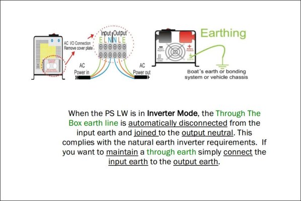
Here is a screenshot of the provided earlier manual said to be for the van in question. It is a pictorial and explanation of the neutral/ground bonding method, but also says the shore safety ground is connected through the inverter itself, not be wiring from the shore cable to the output to van cable, or through the case. It does give you an option to wire it also, it appears, but it would not be required for full 30 safety capacity in the shore safety ground.

Attached Images
File Type: jpg Hymer inverter wiring.jpg (77.8 KB, 262 views)
booster is online now   Reply With Quote
Old 04-04-2018, 06:45 PM   #54
Platinum Member
 
Join Date: Mar 2018
Location: California
Posts: 132
Default

Quote:
Originally Posted by booster View Post
Here is a screenshot of the provided earlier manual said to be for the van in question. It is a pictorial and explanation of the neutral/ground bonding method, but also says the shore safety ground is connected through the inverter itself, not be wiring from the shore cable to the output to van cable, or through the case. It does give you an option to wire it also, it appears, but it would not be required for full 30 safety capacity in the shore safety ground.

I agree. I'd also say that the 18 gauge safety ground in the inverter isn't correct for the inverter's 17.4 amp output
ContinuousImprovement is offline   Reply With Quote
Old 04-04-2018, 06:47 PM   #55
Platinum Member
 
Join Date: Mar 2018
Location: California
Posts: 132
Default

Please add new posts to the thread "Aktiv and Roadtrek Ecotrek are unsafe"
ContinuousImprovement is offline   Reply With Quote
Old 04-12-2018, 05:53 AM   #56
Platinum Member
 
Join Date: Mar 2018
Location: California
Posts: 132
Default Who posted the Roadtrek inverter manual?

Quote:
Originally Posted by booster View Post
Does your inverter look anything like the one in this Aims manual. This was linked in an earlier thread as being a private label unit Roadtrek uses.

http://www.aimscorp.net/documents/PI...0W12V120VR.pdf
SOMEWHERE in the 9 pages we posted in these two threads someone pasted a non-sanitized inverter manual. Its not this QUOTED post and its not the one I posted (attached again) but it looked a like the one I'm posting. Does someone know where that manual is now.
Attached Files
File Type: pdf Inverter Manual - 3000 Rev 2.1.pdf (6.21 MB, 4 views)
ContinuousImprovement is offline   Reply With Quote
Old 04-12-2018, 01:11 PM   #57
Platinum Member
 
Join Date: Aug 2010
Location: Minnesota
Posts: 12,410
Default

That was picked out of another thread, I think posted by Gerrym51 in the Zion or one of the other lithium battery threads, IIRC.
booster is online now   Reply With Quote
Old 04-12-2018, 01:50 PM   #58
Platinum Member
 
Join Date: Mar 2018
Location: California
Posts: 132
Default

Quote:
Originally Posted by gerrym51 View Post
actually i think roadtrek used rebadged aimpower and then started buying them direct from the china supplier to aimspower.

the chinese manufacturer has it's units used all over the world. However they are usually used at fixed sites.

mobile uits are actually a relatively new concept
Hi Gerrym51,
Please read Booster's latest post in this thread. Do you know where the manual is?
ContinuousImprovement is offline   Reply With Quote
Old 04-12-2018, 02:32 PM   #59
Platinum Member
 
Join Date: Dec 2010
Posts: 2,058
Default

Quote:
Originally Posted by ContinuousImprovement View Post
Hi Gerrym51,
Please read Booster's latest post in this thread. Do you know where the manual is?
the only good manual is aimspower .i looked at their site today and they still use re-badged powerstars as their pure sine inverter/chargers. they wrote their own manuals.

since roadtrek now buys direct from powerstar they cannot use aimspower manuals.

they at least give you that useless powerstar sheet. back when i bought they gave me a trip-lite manual which is their base tripp lite 750 they use.

your best bet is still aimspower
gerrym51 is offline   Reply With Quote
Reply

Tags
aktiv, ecotrek, hymer, safety


Posting Rules
You may not post new threads
You may not post replies
You may not post attachments
You may not edit your posts

BB code is On
Smilies are On
[IMG] code is On
HTML code is Off
Trackbacks are Off
Pingbacks are Off
Refbacks are Off


» Featured Campgrounds

Reviews provided by

Powered by vBadvanced CMPS v3.2.3

All times are GMT. The time now is 04:55 PM.


Powered by vBulletin® Version 3.8.8 Beta 4
Copyright ©2000 - 2024, vBulletin Solutions, Inc.