E-Trek Battery Monitor Install

photolimo

Advanced Member
Joined
Dec 12, 2013
Posts
39
I am working on installing a battery monitoring system on our Roadtrek E-Trek. Curious if there is anyone out there with some advice on the subject.

I am planning on installing a Bogart Trimetric on the 24V battery bank to monitor the health of the primary bank. I am a little unsure if there should be a second one on the 12V bank as well. They are electrically connected and have recently been upgraded with a battery balancer.
 

Attachments

  • E-Trek Battery Layout.png
    E-Trek Battery Layout.png
    31 KB · Views: 68
Interesting topic.
Just some thoughts:

I added identifiers in red letters.

E-Trek Battery Layout.jpg

A-,B+ in series = 12v
C-,D+ in series = 12v
ABCD in series = 24v
EFGH in series = 24v
E- ground
B- ground

D+ 24V
H+ 24V
D+,H+ parallels ABCD with EFGH assuming common Sprinter body grounding (B-,E-)

Is B+(6V)?
Is E+(6V)?
I don't understand the B+,E+ union.

F+ looks to me to be 12V+

Would a 24v Trimetric work if one side of the shunt was attached to the metal van body and all loads come off the other side of the shunt? (huge amperage, 200 amps or more possible)

If so, would that catch the 12v flow from balancing activity?
Where does the 12v feed to loads come from?

Would Roadtrek be willing to help with tech advice?

Edit: I'm using the drawing photolimo posted. E-trek owners should not assume that drawing applies to any other E-trek.
 
Last edited:
It is an interesting question to be sure, with the multiple inputs and tapped out different output voltages.

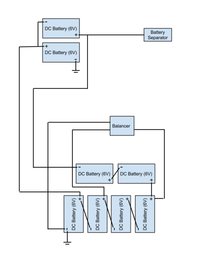
I had made this sketch off of an etrek sketch of their wiring a while ago, and they are very similar.

attachment.php


It may be as simple as tying together the two grounds from the 24v strings and putting the shunt there. That is what you would do for a 24v system. The problem comes in that the Trimetric shunt measures current, and I don't think it will know the difference between 12 and 24 volt current, so 12v use would show the same loss of ah as 24v would.

The way around it may be to take the ground for the balancer and make sure it stays on the chassis, not moved to the battery side of the shunt, as it would be if you just did the two main grounds. Hopefully, with the ground for the balancer on the chassis, the balancer would be running the shunt backwards as the balancer replaced the power used from just the 12v section. Theoretically, if the balancer did nothing on a 12v discharge, all the power would come from the 12v section so they would go down X amount and that is what the meter would see in ah, then the balancer would replace 1/2X into the 12v section from the other batteries, dropping them 1/2X so they were even. The meter would run forwards 1X and backwards for 1/2X so it would end up at the correct 1/2X down on all batteries.

In reality, the balancer is going to be feeding the 12v section as it is actually discharging, but you should get the same results, as the balancer current bypasses the shunt so it wouldn't see it. If the load is small enough that the balancer can keep up, you would have an accurate reading as it discharged, if it was not large enough, your ah down wouldn't be accurate until the balancer caught up.
 
So....
E- grounded to chassis
B- ground removed from chassis (or E- removed and B-grounded, whichever)

E- connected to B- by new heavy gauge wire basically forcing it to be one large series/parallel 8 battery bank at 24v instead of optionally/potentially two 4 battery banks each in series at 24V each then paralleled.

E- balancer wire moved to chassis only

All load and input grounds, both 12 & 24, to be attached to other side of shunt.

Is my understanding of your post accurate so far?

We'd really need to know where the solar and alternator inputs are and where all the load attachments are. The current setup appears to be two 24v banks and 12v loads being directly fed by the balancer and not a simple wire tap but that needs to be confirmed.
 
Last edited:
I wondered if the 6v line was meant to be a balancer - I'd have to research that as I still don't understand how it would give much or any benefit ........

Maybe someone here can explain it.

Loads coming off points other than the balancer would affect Booster's idea I expect.
 
markopolo So....
E- grounded to chassis
B- ground removed from chassis (or E- removed and B-grounded, whichever)

E- connected to B- by new heavy gauge wire basically forcing it to be one large series/parallel 8 battery bank at 24v instead of optionally/potentially two 4 battery banks each in series at 24V each then paralleled.

Yep, B- and E- connected together and to the battery side of the shunt. No other connections to the batteries or the battery side of the shunt, so the shunt sees all the current.

E- balancer wire moved to chassis only

Yep again as we need to shunt to not see any of the 12v that is going from 24v side of the bank to 12v side and to the coach, but the shunt does need to see that current going back into 12v side to the 12v only batteries if the balancer is just balancing and not supporting any load.

All load and input grounds, both 12 & 24, to be attached to other side of shunt.

My guess is that most all the negatives from the loadsand inputs are going to the chassis, and that would stay the same. The chassis would then be connected to non battery side of the shunt. If any loads like the inverter have their negatives directly to the battery, they would need to be moved to the non battery side of the shunt.

Is my understanding of your post accurate so far?

We'd really need to know where the solar and alternator inputs are and where all the load attachments are. The current setup appears to be two 24v banks and 12v loads being directly fed by the balancer and not a simple wire tap but that needs to be confirmed.

I think where the original quote shows the separator tap is also the 12v power tap for the van, but that is just a guess, so then there would be a center tap, like in the sketch of the previous system
 
I wondered if the 6v line was meant to be a balancer - I'd have to research that as I still don't understand how it would give much or any benefit ........

Maybe someone here can explain it.

Loads coming off points other than the balancer would affect Booster's idea I expect.

A+ and C+ are at 12v, it appears, so the only 6v line are in areas of getting two batteries up to 12v like in the engine compartment. The long connection between the single two batteries is just a connection like any others in my sketch and would be at 12v. I think the other wire that goes from the two batteries in the front to the back was in the system we saw before, it was called the balancer, but all it did was tie the two banks together so it had very little real use. It is really just the same as the cable between the + terminals on the batteris connecting the banks in the middle, but those cable are short.

All loads at 12v need to come off the center tap, as there is no other place you get 12v to chassis ground.
 
Last edited:
A+ and C+ are at 12v, .............

Clarify that for me please. It's a few posts back.

I gotta start quoting ........... I'm getting confused. :rolleyes:

Booster - did you see this post:

Yes, B+ and E+ are 6v and labeled "Balancer" on both ends of that HUGE wire.
---------------

Yes, this is where the 12v system hooks in to the 12v fuse panel. Technically it is on A+ but that is connected to F+.

View attachment 2943
 
Clarify that for me please. It's a few posts back.

Should have been C-, not plus at 12v, too much switching back and forth--how do you get the attachments to show in the quotes--that would really help me!

I gotta start quoting ........... I'm getting confused. :rolleyes:

Booster - did you see this post:

The A+ connected to F+ is not on the drawing, unless the intent was to show a connection at C-. If that connection is not there, the system would run on only 2 of the batteries on 12v and the balancer wouldn't see the loaded batteries, so it probably is connected there. It is also probable that there is a connection between G+/H- and C+/D- as that was the way the other system had it.

To use all the batteries correctly, I think the banks need to be connected at H+ to D+, E- to B-, and F+ to A+. G+ to C+ would not be necessary, but nice as the other batteries are connected between banks.
 
The mentioned very large cable between B+ and E+ I think is another of the connections that are not absolutely needed, as it just connects the middle of the two strings of series 12v. It would carry nearly no current if things are right, I would guess. I think if it were my system I would consider taking that cable and using it to parallel up the A+ to F+ connection that was mentioned as being the feed to the 12v panel also. The very long run to the front pair of batteries is going to pretty badly mess up the charging and discharging balance do to voltage drop in the A+ to F+ cable. I think getting less drop in that connection by adding another cable would give way more benefit than where it is shown in the drawing.
 
The mentioned very large cable between B+ and E+ I think is another of the connections that are not absolutely needed .................

I thought the same just before my brain started to quit. Photolimo could check with Roadtrek to see if it just left over from before the installation of an actual balancer.
 
I thought the same just before my brain started to quit. Photolimo could check with Roadtrek to see if it just left over from before the installation of an actual balancer.

I will double check with Roadtrek.

The dealer that installed the new balancer left behind the installation instructions. There was no mention of removing the balancer cable.

I wonder if I could use that cable to hook up the Trimetric battery monitor? Disconnect the 12V ground and attach that balancer to bring it to the shunt in the back.
 

Try RV LIFE Pro Free for 7 Days

  • New Ad-Free experience on this RV LIFE Community.
  • Plan the best RV Safe travel with RV LIFE Trip Wizard.
  • Navigate with our RV Safe GPS mobile app.
  • and much more...
Try RV LIFE Pro Today
Back
Top